
Hager’s Technical Training Manager, Paul Chaffers, shares the importance of observing protective device terminal markings and discusses the requirements for disconnecting all live conductors, including the neutral conductor for certain applications.
Usually, we consider the current flowing through a protective device to be in one direction only, i.e. from the distribution board to the load. But there are requirements to observe for situations where current may flow in either direction through a protective device, such as when a generator is used as an additional source of supply in parallel with another source. For such applications a bidirectional device is required.
The Wiring Regulations specifically make reference to this topic in Chapter 82 for prosumers electrical installations, where Regulation 826.1.2.2 reminds installers to take account of all possible directions of current flow and polarity.
Furthermore, Regulation 134.1.1 requires installers to use proper materials in the erection of electrical installations. Installers must also take account of manufacturers’ instructions for any electrical equipment installed.
Unidirectional
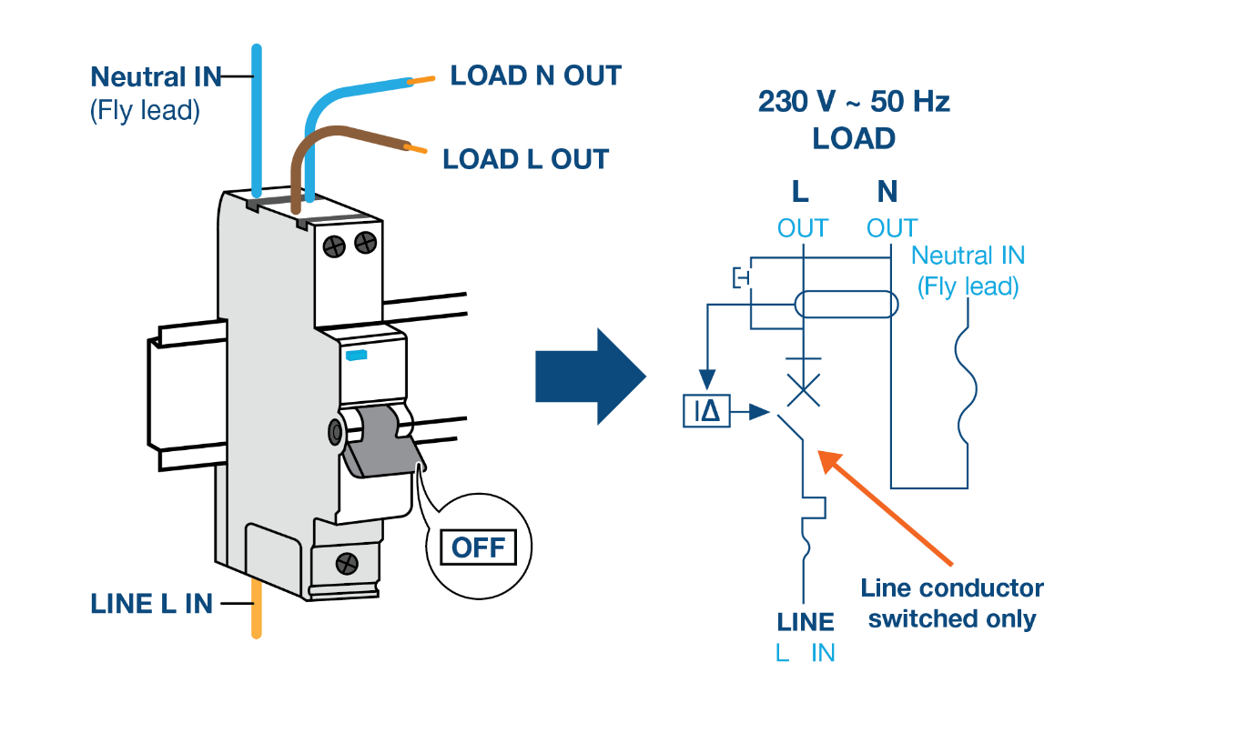
RCD and MCB product standards require that if it is necessary to distinguish between the supply and the load terminals, they shall be clearly marked. Hager unidirectional devices are marked “in” and “out” near the corresponding terminals indicating the direction of power flow. For a better understanding see Fig 1.
Where unidirectional devices are incorrectly used for applications where the current flows in either direction (micro-generation, battery storage, solar PV etc), it is possible that the device can be permanently damaged and therefore may not offer the correct protection under fault conditions.
Bidirectional
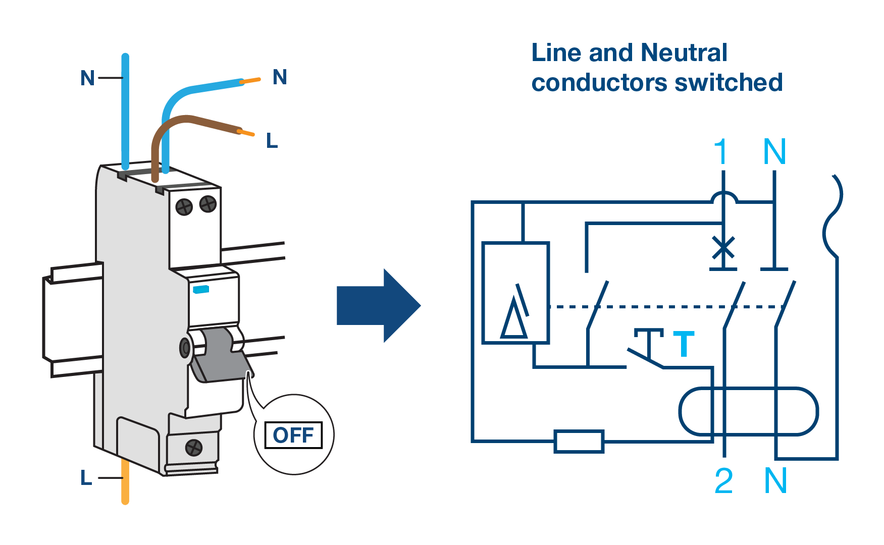
RCDs and MCBs which are NOT marked “in” and “out” or “line” and “load”, or with arrows indicating the direction of power flow, are typically referred to as bidirectional devices and are suitable for all applications where power flow may be in either direction, see Fig 2.
Other considerations
BS 7671 Chapter 55 deals with “other equipment” and it is here where we find extra measures that need to be applied for installations where generating sets may operate in parallel with other sources.
Requirements to disconnect all live conductors
Most existing single modular RCBOs only switch the line conductor, but there are situations where it is necessary to switch all live conductors, including the neutral.
A comparison of the schematic diagrams shown in Figs 1 & 2 will show the differences between Hager’s unidirectional RCBO (single-pole) and the new bidirectional RCBO (double-pole). Similar diagrams are located on the side of each RCBO and in the product data sheets provided in the packaging.
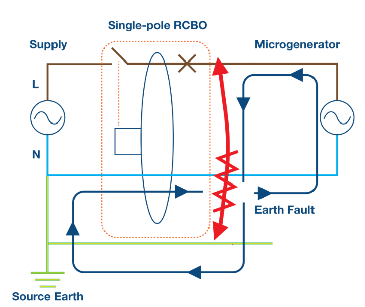
Regulation 551.7.1 requires where an RCD is providing additional protection (in accordance with Regulation 415.1) for a circuit connecting a generator set to the installation, the RCD shall disconnect all live conductors, including the neutral conductor.
Fig 3 shows the reasons why it is important to disconnect all live conductors and the illustration shows an earth fault being fed by a microgenerator after the single-pole RCBO has operated. This will continue for the period of time it takes the microgenerator to shut down due to loss of mains power.
From here we can see that this type of work requires careful design to allow the correct selection of protective devices.
Another example of where the neutral requires switching can be found in Section 722 (Electric vehicle charging installations), where Regulation 722.351.3.1 states RCDs shall disconnect all live conductors.
Designs which include EV to home technology will also require suitable bidirectional protective devices and chargers to allow energy from the EV’s battery back into the home.

Free online CPD
Visit Hager’s Residual Current Devices training course, which covers all of the subjects discussed in this article, plus many more. All technical courses are CPD accredited and come with downloadable certificates.
Get more details on Hager’s RCD training course here
Read more industry technical articles here
FURTHER REFERENCES
To obtain further information regarding current flow direction, see BEAMAs Technical bulletin Connection of Unidirectional and Bidirectional Residual Current Devices (RCDs) and Miniature Circuit-Breakers (MCBs) to power supplies e.g. battery storage, Photovoltaic (PV) systems, Electric Vehicles (EV) to home, a micro-generator, or grid (mains) supply. www.beama.org.uk/resourceLibrary/beama-technical-bulletin—connection-of-unid irectional-and-bidirectional-protective-devices.html
The necessity to disconnect all live conductors is not a new requirement and was addressed in 2007 in the Electrical Safety Council Best Practice Guide on connecting a microgeneration system to a domestic or similar electrical installation (in parallel with the mains supply). www.electricalsafetyfirst.org.uk/professional-resources/best-practice-guides


