
Are you involved directly with heat pump installations or expecting to deal with an existing installation? A better understanding of RCD requirements associated with HPs can save time and money for you and your customers, as Chaz Andrews, Technical Manager at Doepke UK, explains.
ASHPs (air source heat pumps) contain large inverters in comparison to domestic washing machines, for example. Inverter based speed control is central to the economic performance of HP compressors and fans. Inverters also help to reduce compressor starting current peaks, enabling the use of higher kW ratings on single phase supplies, relevant to 90% of UK domestic properties.
In installations requiring RCD protection, HPs must be used with specific types of RCD. HP inverters are not suitable for connection to Type A RCDs. Examples of problems associated with incorrect RCD selection are covered in this article. Aside from being dangerous, HPs that are paired with an unsuitable RCD also lead to the risk of an unreliable heating installation and HP damage.
Guidance
Unlike PV and EV, there is currently no specific guidance given in BS 7671 or the IET Guide (Electrified Heating) relating to HP installation. RCDs connected in circuit with HPs are covered by the generic requirements of Reg 531.3.3. Take note of the HP manufacturer’s grounding and protection recommendations.
*Note: HP designs and supply rating (kW) vary significantly, even between models from the same manufacturer. Some HP designs, due to their operational leakage current, are not suitable for use with 30 mA RCDs. Check with the HP manufacturer first.
The location, external ground mounted and the large exposed conductive part associated with the metal casing, pose an elevated risk in the event of a fault and inappropriate ADS (Reg 411) selection, design and installation.
Where fault disconnection within the required time relies on the operation of an upstream RCD, using the incorrect ‘Type’ of RCD in association with a heat pump leads to the risk of RCD ‘blinding’. The RCD cannot reliably detect fault currents as required by BS 7671, increasing the risk of a fatal accident.
The HP company (equipment specifier) and the installer (electrical) are reliant on each other. This relates to “the duty of care owed to the consumer,” with regard to the combined safety of the equipment and the installation.
HP equipment design characteristics
In installations requiring RCD protection, the characteristics of the inbuilt inverter equipment determine the sensitivity and Type of RCD to be installed up-stream. HP inverters produce AC leakage currents with frequency components above and below 50 Hz, resulting in composite (mixed frequency) residual currents, requiring the application of Type F and B RCDs (see 531.3.3 (ii) & (iii)).
Type A RCDs are designed for operation with sinusoidal or pulsed residual current generated at 50 Hz – Ref 531.3.3 (i). Type A RCDs are not suitable for applications associated with inverters producing composite residual currents.
For those involved in HP design and associated standards committees, see BS EN IEC 62477 H.3: Fault current waveforms produced by speed control inverter topology and the RCD type. This is explained briefly below and relates to the fault currents generated at frequencies less than or greater than 50 Hz under foreseeable fault conditions.
Unwanted tripping of an RCD associated with a HP installation can be the first indication that the incorrect Type of RCD has been installed upstream. Using Type A RCDs outside of the design scope (ref 133.1.3) could result in the device failing to trip when required, or unwanted tripping.
In addition, transients associated with powering up and/or powering down the inverter, can exceed the transient switch-on limit for Type A RCDs, again resulting in unwanted tripping.
*Note: Before carrying out any electrical tests, check the HP manufacturer’s restart procedure. Reconnecting the supply to a HP and running immediately after extended loss of supply can result in serious damage to the compressor.
Can you use Type F with single phase HP?
The characteristics of the HP inverter, and the location of the fault within the equipment, determine the characteristics of the residual current.
The selection of the Type of RCD must consider the fault current scenarios identified in the standards and by the HP manufacturer, in their design risk assessment documentation.
Electrical installers do not have access to the HP manufacturer’s inverter design characteristics and consequently cannot make the decision to use Type F in place of Type B, without the agreement of the HP manufacturer.
The example below is for a common generic scheme associated with single phase supplied – 3 phase out inverter, without power a factor correction stage – ref. source BS EN IEC 62477-1 Fig H.3
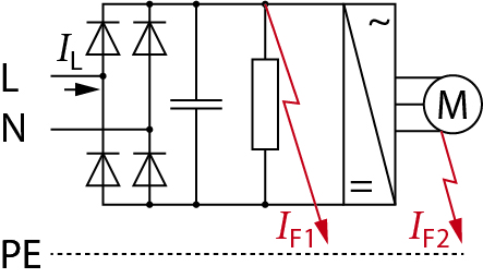
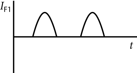
An insulation fault IF1 on the DC side of the bridge rectifier produces a pulsed residual current at the fundamental (mains) frequency. This pulsed current may be superimposed on a smooth DC component, the effective value of which is related to the DC link voltage, smoothing capacitance, and fault resistance.
*Note: Limits for smooth DC fault current: ≤ 10 mA Type F or > 10 mA Type B. Type F RCDs do not trip on smooth DC. Do not use for smooth DC fault current > 10 mA.
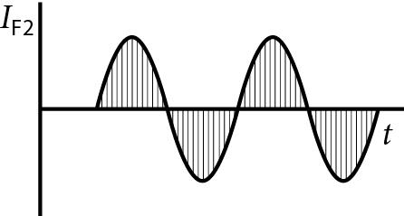
A fault IF2 located on the output stage (supply to motor) results in a residual current containing multiple frequency components. This is referred to as a composite residual current for design/test purposes (see the table below).
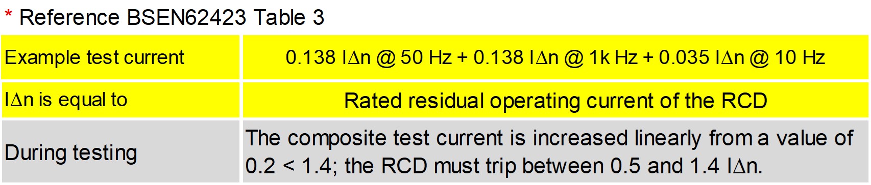
The composite residual current components have relative values defined at the specific frequency; mains frequency, the motor frequency at 10 Hz, and inverter switching frequency at 1 kHz. These values of 10 Hz and 1 kHz represent the most severe condition for Type F RCD tripping, providing reliable operation and effective protection when using Type F RCDs.
HP design limits for use of Type F checked through equipment design calculations and testing:
• Ratio of composite leakages current components compared to RCD sensitivity IAn
• Minimum motor speed control setting (frequency) 10 Hz
• Maximum inverter switching frequency <1kHz
• Maximum smooth dc fault current limit <10mA
If the equipment design characteristics cannot be guaranteed to meet the Type F limits, use Type B instead. Single phase supplied speed control inverters with power factor correction stages and 3 phase supplied inverters, must only be used with Type B RCDs – see additional diagrams and recommendations in BS EN IEC 62477-1H.3.
Type B RCD unexplained tripping
Modern HP inverters with switching frequency in the region of 2 < 16 kHz naturally produce higher leakage currents at higher frequency (circuit capacitance Xc is indirectly proportional to frequency). The switching frequency is factory set, based on the required HP operating characteristics. A number of manufacturers’ Type B RCDs are only designed to work < 1 kHz i.e. above 1 kHz the tripping characteristic is undefined.
The RCD may trip unexpectedly when subjected to lower values of leakage current than those required at 1 kHz by BS EN 62423. This can manifest itself in unexplained tripping events of some Type B RCDs associated with a HP. Refer to the manufacturer’s Type B RCD technical characteristics to verify their suitability for use with leakage currents generated by the HP inverter at frequencies > 1 kHz.
Conclusion
Greener homes require smarter solutions (equipment) than those traditionally associated with the simplicity of our old domestic installations. This, in turn, requires a better knowledge of the individual characteristics of the equipment we’re intending to supply with electricity. A bit of planning, checking and verification before attending site is a pre-requisite for quick, safe and reliable installation.
As with any complex equipment, HP characteristics vary from one manufacturer to another. Consequently, the design of the electrical supply requirements and associated protection devices may differ. This must be considered in conjunction with the individual site design requirements, based on BS 7671. It is simple if you do it right – look, check, ask, think, do!
To operate reliably and provide years of trouble-free service, HPs require a reliable electrical supply. The duty of care is shared between the HP manufacturer/UK supplier and the electrical installer. This can be met with a bit of planning, checking and discussion, if necessary, prior to installation.
Big metal boxes mounted outside and supplied with electricity represent a potential hazard. To reduce the risk of an accident, the electrical installation and method of protection (ADS), must meet the specific requirements of BS 7671, to the letter.
Get more details about Doepke’s range of RCDs and circuit protection products here
Read more industry technical articles here


