
Jake Green, Head of Technical Engagement at Scolmore Group, briefly considers one aspect of selectivity as it relates to overcurrent protective devices (OCPD), and in particular circuit-breakers conforming to BS EN 60898.
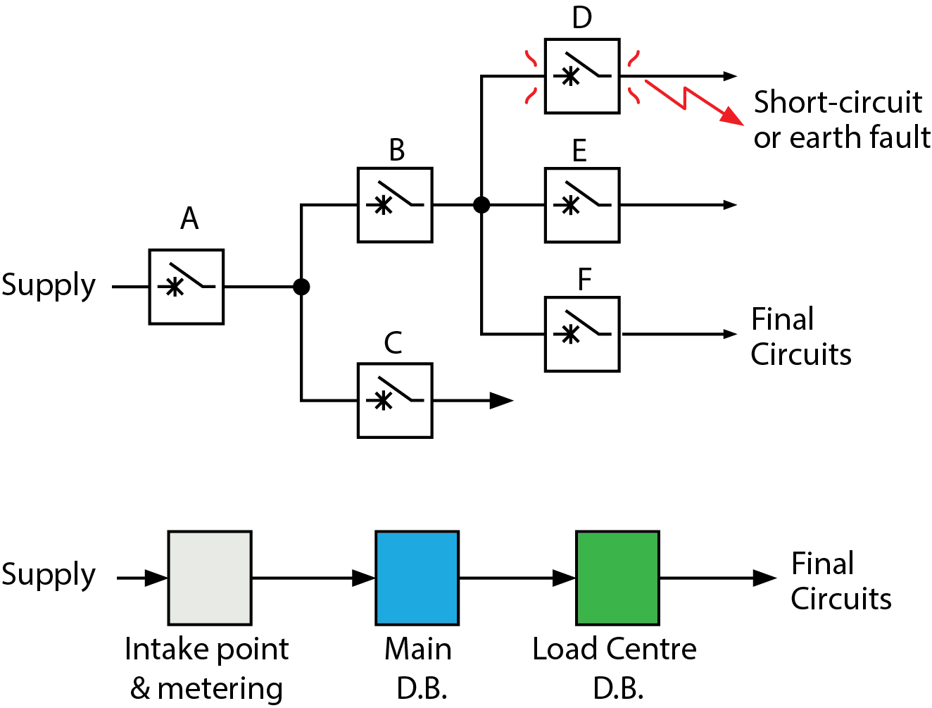
Selectivity is one element that designers must consider as part of the coordination requirement detailed in Regulation 536.3 (Fig 1).
Selectivity is defined as, ‘Coordination of the operating characteristics of two or more protective devices such that, on the incidence of an overcurrent or residual current within stated limits, the device intended to operate within these limits does so, while the other(s) does (do) not.’
General requirements
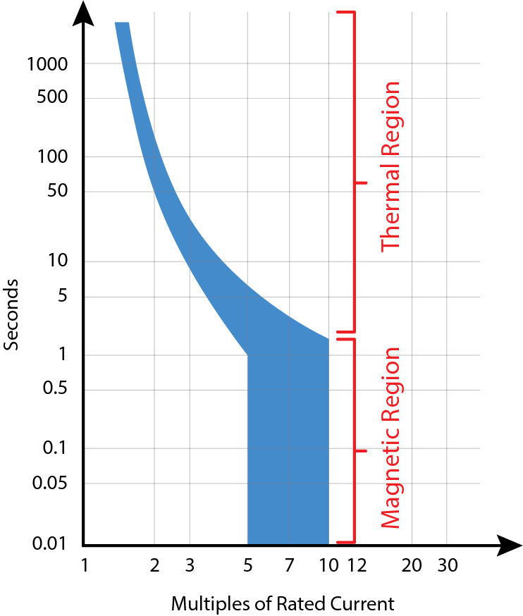
The disconnection of circuit-breakers is caused by either electro-magnetic release or by thermal bi-metallic release (Fig 2). The electro-magnetic release is considered to be ‘instantaneous’ and is wholly dependent on current, while the thermal release depends on both current and time as temperature rises.
Whether overload is likely to occur depends on the nature of the load and will not be considered in this article. Under conditions where overload isn’t likely to exist, the only condition requiring consideration is short-circuit, whether that be between live conductors or to earth.
Selectivity for overload conditions is detailed in Regulation 536.4.1.2 and for short-circuit conditions in Regulation 536.4.1.3.
The designer should take account of the reference ambient temperature (30 ̊C) for the tripping curves and the load conditions before the overcurrent. Manufacturers should be prepared to give information on the variation of the tripping characteristics where the ambient temperature differs significantly from the standard value (Clause 8.6.3.1).
Selectivity is either:
1. Partial – this occurs where, in the presence of two overcurrent protective devices in series, the downstream protective device affects the protection up to a given level of overcurrent, without causing the upstream device to operate.
2. Total – this occurs where, in the presence of two overcurrent protective devices in series, the downstream protective device affects the protection without causing the upstream device to operate.
Short circuit conditions
When determining selectivity between circuit-breakers it’s necessary to consult the data issued by manufacturers. Clause D.4 of the informative Annex D in BS EN 60898 makes it clear that, on request, the manufacturer of the circuit-breaker will provide information on the type and the characteristics of the short-circuit protective device to be used with the downstream device.
The standard ranges of instantaneous tripping of circuit-breakers conforming to BS EN 60898 (clause 5.3.5) are shown in Table 1, below.
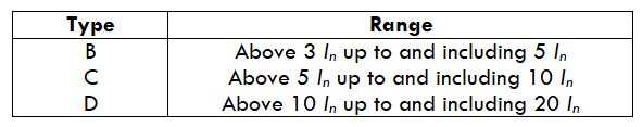
For example, for a 10 A (In) type B circuit-breaker:
• At 3 x 10 (30 A) the circuit-breaker will not trip instantaneously but will trip after a certain period as the thermal element operates (overload conditions).
• At 5 x 10 (50 A) the circuit-breaker will trip instantaneously (electro-magnetic release).
• At values between just above 30 A and below 50 A, the circuit-breaker may operate on the electro-magnetic release or on the thermal trip.
Annex D (informative) of BS EN 60898 provides guidance on co-ordination under short-circuit conditions between a circuit-breaker and another short-circuit protective device associated in the same circuit.
For partial selectivity, the current causing the instantaneous operation of the downstream device (instantaneous tripping current) must be less than selectivity limit current (Is) of the upstream device.
By way of example, consider the following:
Question: A 20 A Type B circuit-breaker conforming to BS EN 60898 supplies a load not subject to overload conditions. What will be the minimum rating of the upstream device likely to provide partial selectivity?
Answer: The instantaneous tripping current of a 20 A device is 5 × 20 = 100 A (5 In). Assuming an upstream device of rating 32 A, the selectivity limit current (Is) must not be less than 100 A. That is, the device is required to not operate at 3 In. This equates to a fault current exceeding 3 × 32 = 96 A.
A 32 A type B circuit-breaker wouldn’t provide selectivity, as at 96 A the 32 A device (Fig 3, Blue and Green band) overlaps with the instantaneous tripping current of the 20 A device.
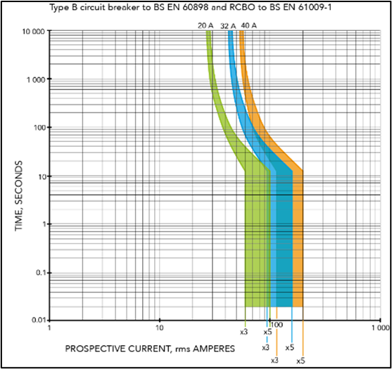
It’s necessary, therefore, to increase the upstream rating to at least 40 A to provide partial selectivity (Fig 3, Orange and Green band). Fig 3 also shows that there’s clear space between the lower limit of the 40 A device (120 A) with the 20 A device (100 A), hence partial selectivity.
Even where partial selectivity exists, where the fault current (short-circuit) is of a value that exceeds the instantaneous tripping value of the upstream device as well as the downstream device, both protective devices may still operate simultaneously.
If selectivity cannot be achieved by current difference, for example between two quick acting circuit-breakers having similar reaction times, selectivity is to be realised by having some form of time delay.
In conclusion, designers should be aware of their responsibility to provide suitable coordination for devices. With protective devices this includes the requirement, where practicable, to create conditions for either partial or total selectivity.
The study of selectivity is a complicated one and this article can only provide a simple introduction to certain aspects of coordination.
Read more industry technical articles here


